LibIHT-Background Information
This blog post will provide some background information on the hardware features that LibIHT will be using to collect branch information. It is heavily referenced from the Intel 64 and IA-32 Architectures Software Developer Manuals in the Reference section.
If you are really interested in the details, we would recommend reading the manuals. They are very detailed and provide a lot of information on the hardware features that LibIHT will be using.
Intel Hardware Tracing Features
Intel processors have several hardware features that can be used to collect branch information. These features are super useful for debugging and performance analysis. They are originally designed for branch profiling and program optimization purposes. But with proper software implementation, they can be used for other purposes as well.
Note: This blog will contain a general overview of the features. Some of features, depending on the processor their microarchitecture, may have slightly different implementations. If you are a hardware enthusiast, we strongly recommend reading the manuals before using these features.
Non-Architectural Last Branch Record (LBR)
This section mostly references the Intel 64 and IA-32 Architectures Software Developer Manuals Volume 3, Chapter 18.4.1, 18.4.2, and 18.4.8.
Note: There is also a newer version of LBR feature in latest Intel processors, called Architectural LBR. They are two different features. However, this blog post will only focus on the Non-Architectural one and will use the term LBR to refer to it.
The Non-Architectural Last Branch Record (LBR) was first introduced on P6 family processors to allow the ability to set breakpoints on taken branches, interrupts, and exceptions, and to single-step from one branch to the next. This feature also been extended in later processors: Pentium 4, Intel Xeon, Pentium M, Intel® Core™ Solo, Intel® Core™ Duo, Intel® Core™2 Duo, Intel® Core™ i7 and Intel Atom®.
LBR Overview
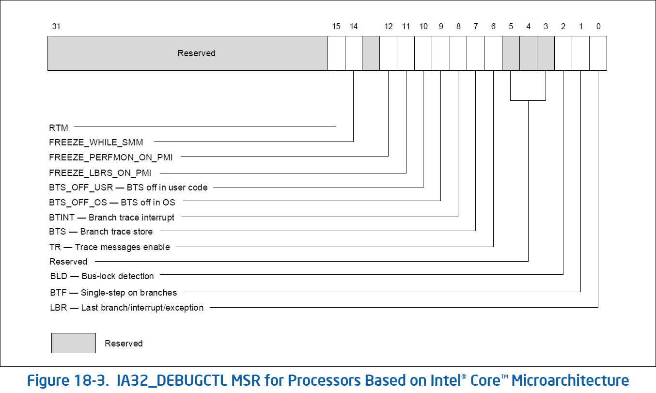
The IA32_DEBUGCTL MSR (Model Specific Register) provides bit field controls to enable debug trace interrupts, debug trace stores, trace messages enable, single stepping on branches, last branch record recording, and to control freezing of LBR stack or performance counters on a PMI (Performance Monitor Interrupt) request. This MSR is located at register address 1D9h.
Specifically, when the LBR flag (bit 0) in the IA32_DEBUGCTL MSR is set, the processor automatically begins recording branch records for taken branches, interrupts, and exceptions (except for debug exceptions) in the LBR stack MSRs
For more detailed information about other bits on the IA32_DEBUGCTL MSR, see Appendix A.
LBR Stack
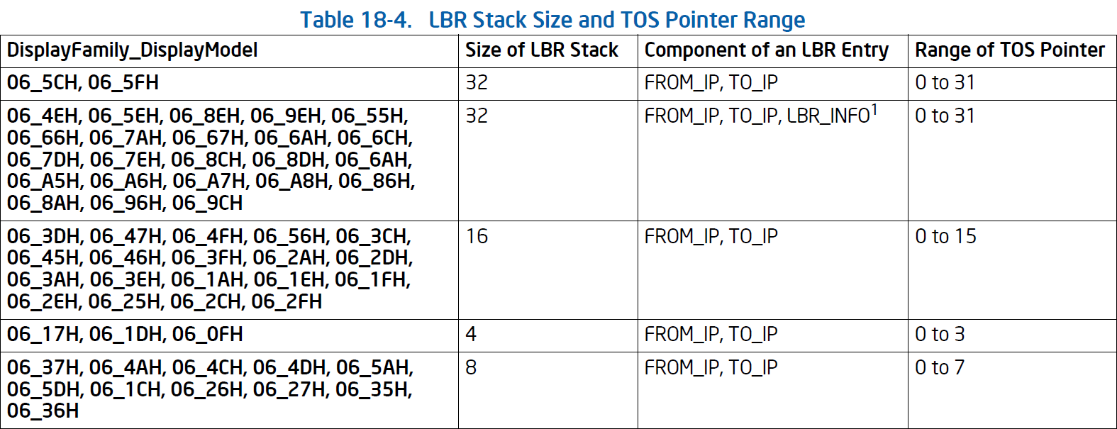
The LBR mechanism stores each branch record in pair of MSRs: MSR_LASTBRANCH_x_FROM_IP and MSR_LASTBRANCH_x_TO_IP. One pair of MSRs is an entry in the LBR stack. The x in the MSR name is the index on the LBR stack, ranging from 0 to N-1, where N is the number of entries in the LBR stack. The FROM_IP MSR contains the source instruction pointer of the branch, and the TO_IP MSR contains the destination instruction pointer of the branch.
Top-of-Stack (TOS) MSR
There is also a top-of-stack MSR called MSR_LASTBRANCH_TOS. It contains the top of the stack by index. It indicates the most recent branch, interrupt, or exception recorded.
The last branch record stack and top-of-stack pointer MSRs are supported across Intel 64 and IA-32 processor families. However, the number of MSRs in the LBR stack and the valid range of TOS pointer value can vary between different processor families.
LBR Filtering
Not all processors and their microarchitectures support the filtering of the LBR stack. According to the manual, here is a list of processors that support LBR filtering:
- Intel Atom® processors based on Silvermont microarchitecture
- Processors based on Goldmont and Goldmont Plus microarchitectures
- Intel Xeon® Phi processor 7200/5200/3200
- Processors based on Nehalem microarchitecture
- Processors based on Sandy Bridge microarchitecture
- Processors based on Haswell microarchitecture
- Processors based on Skylake microarchitecture
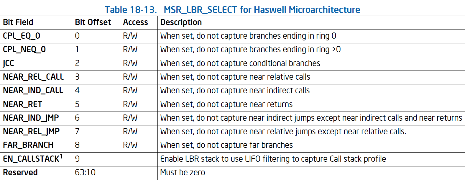
In general, for those processors that support LBR filtering, they use the MSR_LBR_SELECT MSR to control the filtering of the LBR stack. Most of the main filtering functionalities are very similar, here is a table for Haswell microarchitecture:
Other microarchitectures’ filtering mechanisms are subset of this table. The main difference happens in the bit 6, 7, and 9 of the MSR_LBR_SELECT MSR.
Branch Trace Store (BTS)
This section mostly references the Intel 64 and IA-32 Architectures Software Developer Manuals Volume 3, Chapter 18.4.1, 18.4.4, and 18.4.9.
The Branch Trace Store (BTS) feature is a powerful extension of the LBR feature. The manual itself did not mention the exact processor family that supports BTS. However, it is safe to assume that it is supported in processors that support LBR feature because they both act as a debugging and branch profiling hardware features on Intel processors.
BTS Overview
Recall that in LBR Overview, we mentioned that the IA32_DEBUGCTL MSR provides bit field controls to some of the hardware debugging features, this also includes the BTS feature.
When the BTS flag (bit 7) in the IA32_DEBUGCTL MSR is set, the processor enables the BTS facilities to log branch trace messages (BTMs) to a memory-resident BTS buffer that is part of the DS save area.
To actually enable the BTS feature, set the BTS flag is not enough. You also need to set the TR flag (bit 6) in the IA32_DEBUGCTL MSR. The TR flag enables the branch trace messages (BTMs) to be sent out on the system bus. The BTM contains the source and destination instruction pointers of the branch, interrupt, or exception.
As we observed, there are still some flags that related to the BTS feature but not mentioned here, we will cover more detailed information in the following sections. You can also check the Appendix A for more information.
DS Mechanism
The Debug Store (DS) feature flag (bit 21) can be accessed by CPUID.1:EDX[21]. The flag indicates that the processor provides the DS mechanism. This allows BTMs to be logged to a memory-resident BTS buffer. It also allows processor event-based sampling (PEBS) to use the DS Area. Since this feature (PEBS) is not been used in LibIHT (but we hope we can implement it in the future), we will not cover this feature in this blog post. But feel free to checkout the manual in chapter 20.6.2.4 for more detailed information.
When DS flag is set, the BTS_UNAVAILABLE and PEBS_UNAVAILABLE flags in the IA32_MISC_ENABLE MSR indicate (when clear) the availability of the BTS and PEBS facilities, including the ability to set the BTS and BTINT bits in the IA32_DEBUGCTL MSR. Also, it needs the IA32_DS_AREA MSR exist and points to the DS save area.
DS Save Area
The DS save area is a software-designated area that used to collect the following two types of information:
- Branch records — When the BTS flag is set in the
IA32_DEBUGCTLMSR, a branch record is stored in the BTS buffer in the DS save area whenever a taken branch, interrupt, or exception is detected. - PEBS records — When a performance counter is configured for PEBS, a PEBS record is stored in the PEBS buffer in the DS save area after the counter overflow occurs. (For more information about PEBS, please refer to the manual.)
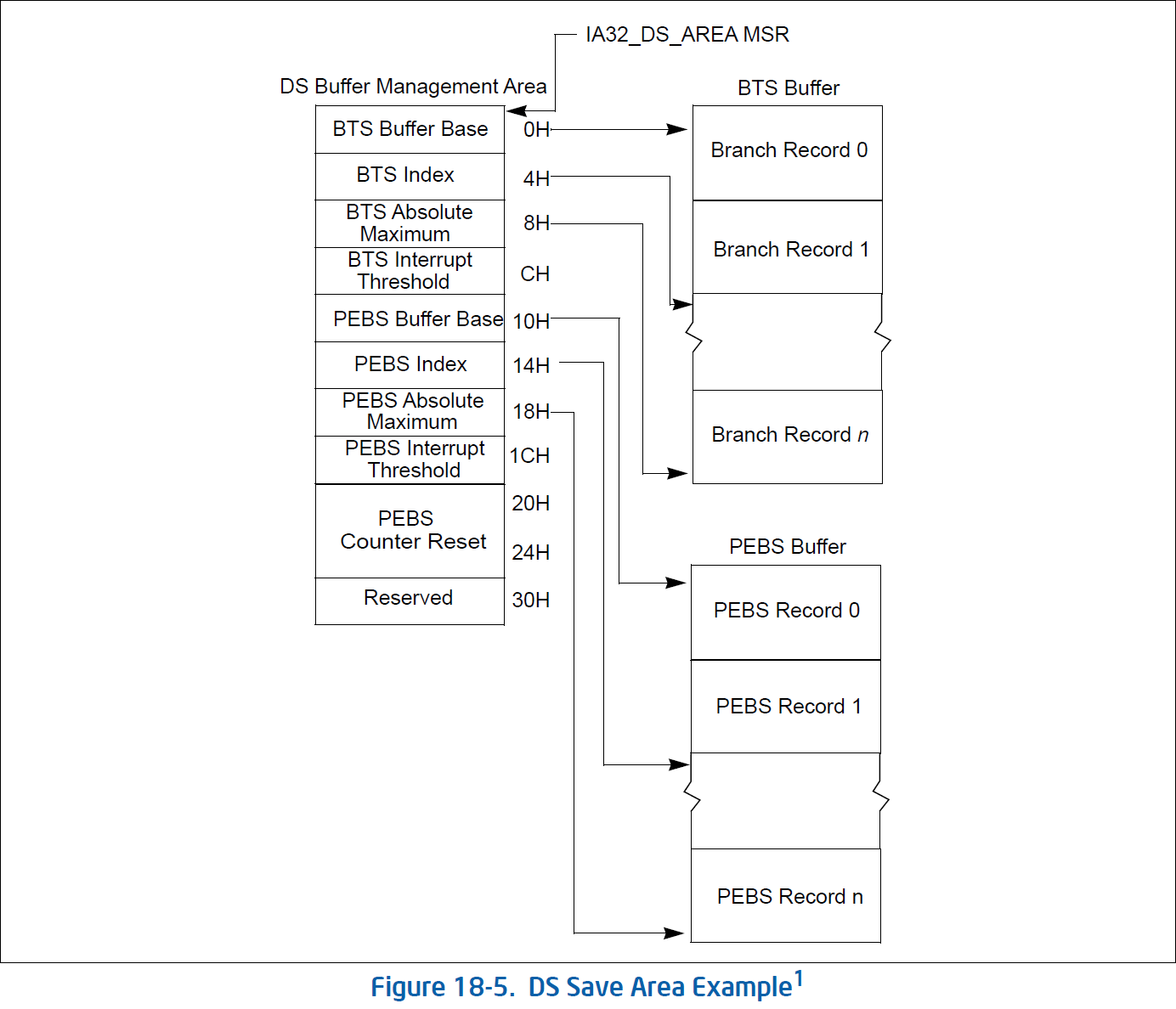
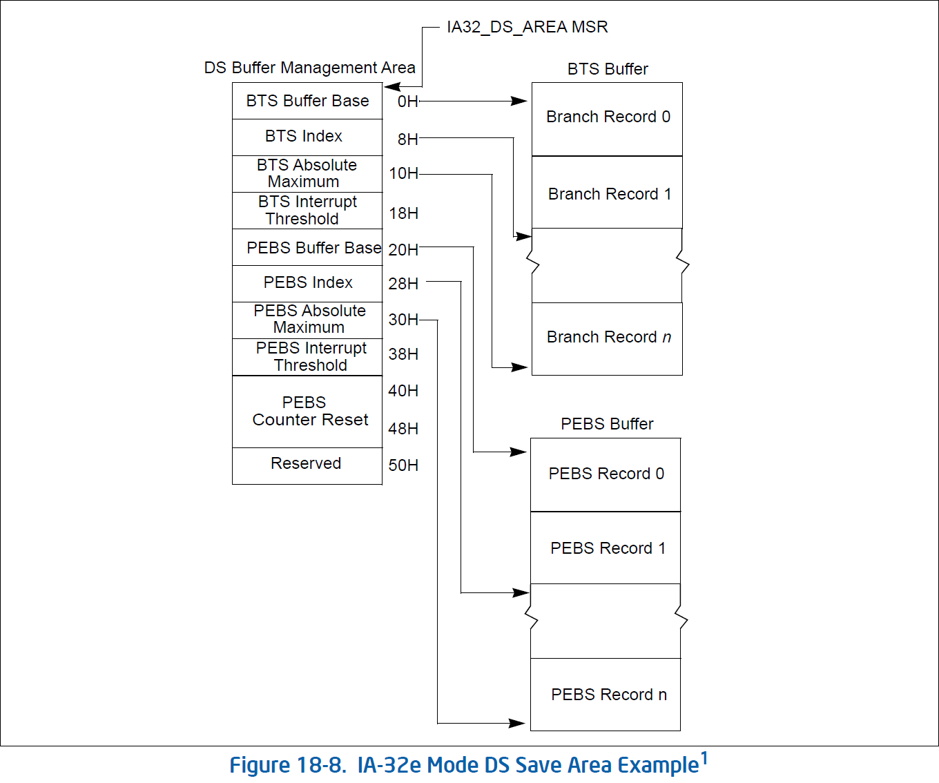
The DS save area is divided into three parts: buffer management area, BTS buffer, and PEBS buffer. Buffer management area it used to define the size and location of the BTS and PEBS buffers. The processor then uses the buffer management area to keep track of the branch and/or PEBS records in their respective buffers and to record the performance counter reset value. The linear address of the first byte of the DS buffer management area is specified with the IA32_DS_AREA MSR.
32-bit version of the DS save area:
64-bit version of the DS save area:
As the graph here is very straightforward, I will put the detailed information in the Appendix B.
The BTS buffer is used to store the branch trace records. In addition to the LBR style branch records (with source and destination instruction pointers), the BTS buffer contains an entry for whether the branch that was taken was predicted or not predicted.
32-bit version of the BTS record:
64-bit version of the BTS record:
Setting Up DS Save Area
To actually enable the BTS feature, you need to correctly set up the DS save area by the following procedures (This is not the exact precise steps, but it should give you a general idea, please refer to the manual for more detailed information):
- Allocate a memory region for the DS buffer management area, BTS buffer, and PEBS buffer (optional if no need for PEBS).
- Configure the DS buffer management area with the correct information (pointers, etc.).
- Write the linear address of the DS buffer management area to the
IA32_DS_AREAMSR. - (Optional) Write the interrupt service routine to handle the BTS interrupt when the BTS buffer is full.
- Enable the BTS feature by setting the BTS flag, TR flag, and probably other filtering flags in the
IA32_DEBUGCTLMSR.
The following restrictions apply to the DS save area (Copied from the manual):
- The recording of branch records in the BTS buffer (or PEBS records in the PEBS buffer) may not operate properly if accesses to the linear addresses in any of the three DS save area sections cause page faults, VM exits, or the setting of accessed or dirty flags in the paging structures (ordinary or EPT). For that reason, system software should establish paging structures (both ordinary and EPT) to prevent such occurrences. Implications of this may be that an operating system should allocate this memory from a non-paged pool and that system software cannot do “lazy” page-table entry propagation for these pages.
- The DS save area can be larger than a page, but the pages must be mapped to contiguous linear addresses. The buffer may share a page, so it need not be aligned on a 4-KByte boundary. For performance reasons, the base of the buffer must be aligned on a doubleword boundary and should be aligned on a cache line boundary.
- It is recommended that the buffer size for the BTS buffer and the PEBS buffer be an integer multiple of the corresponding record sizes.
- The precise event records buffer should be large enough to hold the number of precise event records that can occur while waiting for the interrupt to be serviced.
- The DS save area should be in kernel space. It must not be on the same page as code, to avoid triggering selfmodifying code actions.
- There are no memory type restrictions on the buffers, although it is recommended that the buffers be
designated as WB memory type for performance considerations. - Either the system must be prevented from entering A20M mode while DS save area is active, or bit 20 of all addresses within buffer bounds must be 0.
- Pages that contain buffers must be mapped to the same physical addresses for all processes, such that any change to control register CR3 will not change the DS addresses.
- The DS save area is expected to used only on systems with an enabled APIC. The LVT Performance Counter entry in the APCI must be initialized to use an interrupt gate instead of the trap gate.
In short, those restrictions are mainly about the memory management and the buffer size. If you follow the normal convention of memory management, you should be fine (Just as what we did in LibIHT). It is important to follow those restrictions to ensure the BTS feature works properly.
Setting Up BTS Buffer
There are three flags in the IA32_DEBUGCTL MSR that are related to the BTS feature: TR, BTS, and BTINT.
- The TR flag enables the branch trace messages (BTMs) to be sent out on the system bus.
- The BTS flag enables the BTS facilities to log BTMs to a memory-resident BTS buffer that is part of the DS save area.
- The BTINT flag generates an interrupt when the BTS buffer is nearly full.
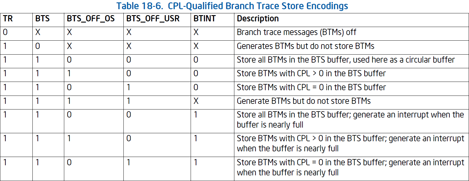
The correct and allowed combination of these three flags is shown in the following table:
Note: If the buffer size is set to less than the minimum allowable value (i.e., BTS absolute maximum < 1 + size of BTS record), the results of BTS is undefined.
In order to prevent generating an interrupt, when working with circular BTS buffer, SW need to set BTS interrupt threshold to a value greater than BTS absolute maximum (fields of the DS buffer management area). It’s not enough to clear the BTINT flag itself only.
BTS Filtering
Similar to the LBR feature, BTS also provides filtering mechanisms to filter the branch records. If the processor supports CPL-qualified last branch recording mechanism, the generation of branch records and storing of them in the BTS buffer are determined by: TR, BTS, BTS_OFF_OS, BTS_OFF_USR, and BTINT.
Conclusion
In conclusion, the LBR and BTS features are powerful hardware features that can be used to collect detailed branch information, which can not only be used for debugging, branch profiling, and program optimization but also for reverse engineering to understand the control flow of a program. LibIHT empower these features to reverse engineers and security researchers to collect branch information for their analysis. We will talk more about how LibIHT uses these features and how it’s been architected in the future blog posts.
You can also checkout the github repository of LibIHT here. Feel free to star the repository if you are interested in the project. Issues and pull requests are also welcome!
Reference
Appendix
The Appendix section is used to provide additional information copied from the Intel 64 and IA-32 Architectures Software Developer Manuals. It is not necessary to read this section unless you are really interested in the details.
Appendix A: IA32_DEBUGCTL
LBR (last branch/interrupt/exception) flag (bit 0) — When set, the processor records a running trace of the most recent branches, interrupts, and/or exceptions taken by the processor (prior to a debug exception being generated) in the last branch record (LBR) stack. For more information, see the Section 18.5.1, “LBR Stack” (Intel® Core™2 Duo and Intel Atom® processor family) and Section 18.9.1, “LBR Stack” (processors
based on Nehalem microarchitecture).BTF (single-step on branches) flag (bit 1) — When set, the processor treats the TF flag in the EFLAGS register as a “single-step on branches” flag rather than a “single-step on instructions” flag. This mechanism allows single-stepping the processor on taken branches. See Section 18.4.3, “Single-Stepping on Branches,” for more information about the BTF flag.
BLD (bus-lock detection) flag (bit 2) — If this bit is set, OS bus-lock detection is enabled when CPL > 0. See Section 18.3.1.6.
TR (trace message enable) flag (bit 6) — When set, branch trace messages are enabled. When the processor detects a taken branch, interrupt, or exception; it sends the branch record out on the system bus as a branch trace message (BTM). See Section 18.4.4, “Branch Trace Messages,” for more information about the
TR flag.BTS (branch trace store) flag (bit 7) — When set, the flag enables BTS facilities to log BTMs to a memory-resident BTS buffer that is part of the DS save area. See Section 18.4.9, “BTS and DS Save Area.”
BTINT (branch trace interrupt) flag (bit 8) — When set, the BTS facilities generate an interrupt when the BTS buffer is full. When clear, BTMs are logged to the BTS buffer in a circular fashion. See Section 18.4.5, “Branch Trace Store (BTS),” for a description of this mechanism.
BTS_OFF_OS (branch trace off in privileged code) flag (bit 9) — When set, BTS or BTM is skipped if CPL is 0. See Section 18.13.2.
BTS_OFF_USR (branch trace off in user code) flag (bit 10) — When set, BTS or BTM is skipped if CPL is greater than 0. See Section 18.13.2.
FREEZE_LBRS_ON_PMI flag (bit 11) — When set, the LBR stack is frozen on a hardware PMI request (e.g., when a counter overflows and is configured to trigger PMI). See Section 18.4.7 for details.
FREEZE_PERFMON_ON_PMI flag (bit 12) — When set, the performance counters (IA32_PMCx and IA32_FIXED_CTRx) are frozen on a PMI request. See Section 18.4.7 for details.
FREEZE_WHILE_SMM (bit 14) — If this bit is set, upon the delivery of an SMI, the processor will clear all the enable bits of IA32_PERF_GLOBAL_CTRL, save a copy of the content of IA32_DEBUGCTL and disable LBR, BTF, TR, and BTS fields of IA32_DEBUGCTL before transferring control to the SMI handler. If Intel Thread Director support was enabled before transferring control to the SMI handler, then the processor will also reset the Intel Thread Director history (see Section 15.6.11 for more details about Intel Thread Director enable, reset, and history reset operations).
Subsequently, the enable bits of IA32_PERF_GLOBAL_CTRL will be set to 1, the saved copy of IA32_DEBUGCTL prior to SMI delivery will be restored, after the SMI handler issues RSM to complete its service. If Intel Thread Director support is enabled when RSM is executed, then the processor resets the Intel Thread Director history.
Note that system software must check if the processor supports the IA32_DEBUGCTL.FREEZE_WHILE_SMM control bit. IA32_DEBUGCTL.FREEZE_WHILE_SMM is supported if IA32_PERF_CAPABILITIES. FREEZE_WHILE_SMM[Bit 12] is reporting 1. See Section 20.8 for details of detecting the presence of IA32_PERF_CAPABILITIES MSR.RTM (bit 15) — If this bit is set, advanced debugging of RTM transactional regions is enabled if DR7.RTM is also set. See Section 18.3.3.
Appendix B: DS Save Area (Buffer Management Area)
BTS buffer base — Linear address of the first byte of the BTS buffer. This address should point to a natural doubleword boundary.
BTS index — Linear address of the first byte of the next BTS record to be written to. Initially, this address should be the same as the address in the BTS buffer base field.
BTS absolute maximum — Linear address of the next byte past the end of the BTS buffer. This address should be a multiple of the BTS record size (12 bytes) plus 1.
BTS interrupt threshold — Linear address of the BTS record on which an interrupt is to be generated. This address must point to an offset from the BTS buffer base that is a multiple of the BTS record size. Also, it must be several records short of the BTS absolute maximum address to allow a pending interrupt to be handled prior to processor writing the BTS absolute maximum record.
PEBS buffer base — Linear address of the first byte of the PEBS buffer. This address should point to a natural doubleword boundary.
PEBS index — Linear address of the first byte of the next PEBS record to be written to. Initially, this address should be the same as the address in the PEBS buffer base field.
PEBS absolute maximum — Linear address of the next byte past the end of the PEBS buffer. This address should be a multiple of the PEBS record size (40 bytes) plus 1.
PEBS interrupt threshold — Linear address of the PEBS record on which an interrupt is to be generated. This address must point to an offset from the PEBS buffer base that is a multiple of the PEBS record size. Also, it must be several records short of the PEBS absolute maximum address to allow a pending interrupt to be handled prior to processor writing the PEBS absolute maximum record.
PEBS counter reset value — A 64-bit value that the counter is to be set to when a PEBS record is written. Bits beyond the size of the counter are ignored. This value allows state information to be collected regularly every time the specified number of events occur.
